CIV102 TRUSS BRIDGE DESIGN [November 2012]
Overview
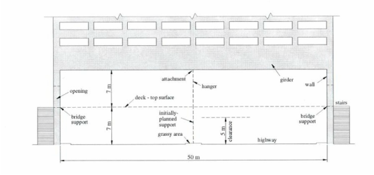
This CIV102 (Structures and Materials) Project required us to design a 50 m long pedestrian truss bridge hanging underneath a building, over a highway. As a team of engineers, we were required to provide a design for the truss bridge based on statics calculations for each load member of the bridge, and to justify the selection of our design.
This CIV102 (Structures and Materials) Project required us to design a 50 m long pedestrian truss bridge hanging underneath a building, over a highway. As a team of engineers, we were required to provide a design for the truss bridge based on statics calculations for each load member of the bridge, and to justify the selection of our design.
|
Team members: Arthur Brown Colin Tong Shaishav Shah |
|
Preparation and Conceptualization
The main objective of this project was to get us to understand the designing process that goes into building a real bridge, and the approximate costs involved with it. Also, this was done to sharpen understanding about trusses and how to accomplish the various calculations attached with it. We were provided with the constraint to have at least one hanger in between to ensure that students realize the importance of dividing bridges into multiple spans in order to get an optimum design. Important consideration had to be given to the stakeholders, considering the cost involved with such a project and the importance. We identified the stakeholders as being the construction company, the pedestrians, the City Council and the building owner. These would be affected the most by such a bridge underneath the building.
Our team discussed the pros and cons of making a two-span or three-span bridge and decided to design a two-span bridge with a hanger in the middle connecting the bridge to the base of the building, as was required by the project brief. For the 10-page report we were supposed to submit, we had detailed calculations for the more important sections such as the calculating the forces that each truss member had to hold and the midspan deflection of the bridge under the loads. Additionally, we showed sample calculations for the member selections, wind load design, elongation of the hanger, natural frequency and the self-weight comparison with the provided value of 0.70 kN/m2.
In the end, if constructed, our bridge would cost ~$60, 000 to make. This was one of the cheaper designs compared to the other designs that were presented in class.
Reflection
From the feedback we received from our TA, we had done a pretty good job designing our bridge, and we had complied with most of the constraints of the project. However, we had incorrectly calculated the wind load design for the bottom truss, as we designed for a quarter of the bridge and by symmetry, provided the same values to the other three-quarters, although we had to do wind bracing for an entire span of the bridge, and use symmetry for the other half of the bridge.
Another mistake we made was regarding the calculations for bracing system to prevent top chord buckling of trusses. We had no calculations for these at all! We had considered wind bracing for the top chord instead, which would be correct if the buckling load would be less than the wind load; however, that is not usually the case.
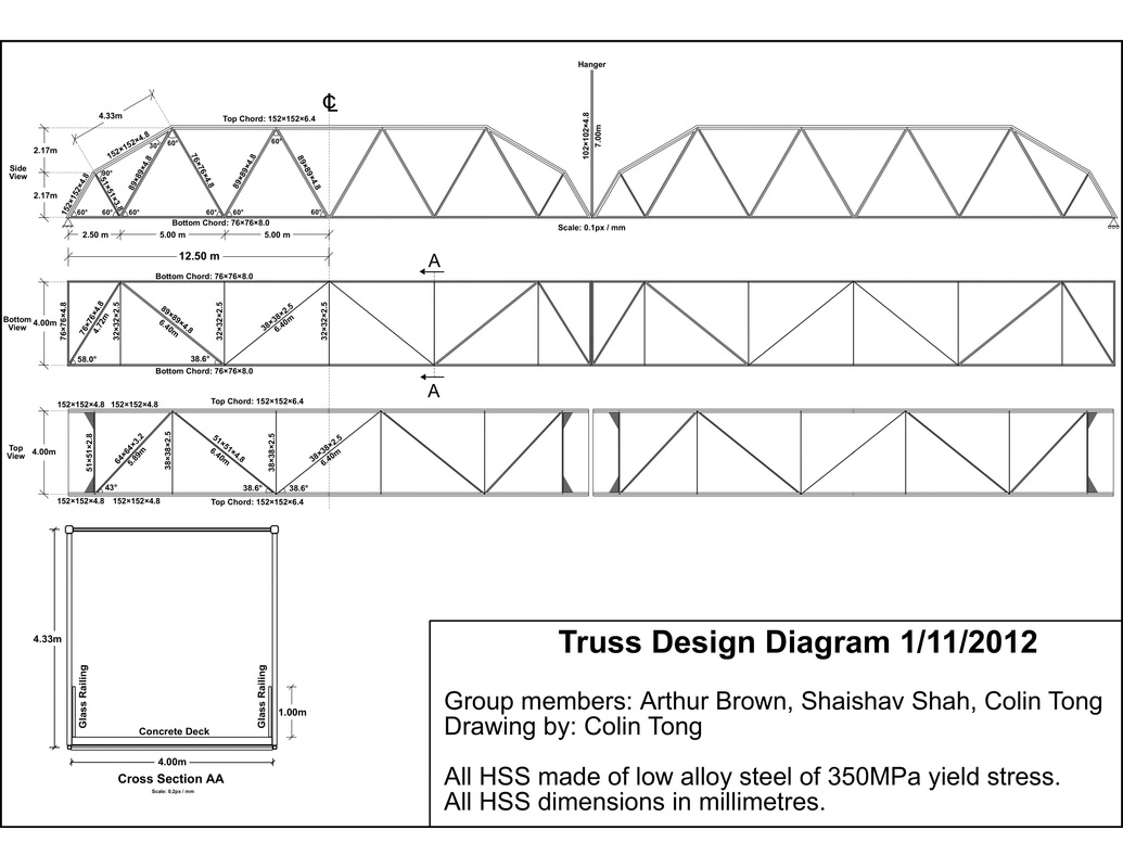
On the whole, our bridge did pretty well as we had stated our assumptions clearly and remained within the constraints of the project, and provided an excellent engineering drawing for the bridge (which can be viewed below).
The main objective of this project was to get us to understand the designing process that goes into building a real bridge, and the approximate costs involved with it. Also, this was done to sharpen understanding about trusses and how to accomplish the various calculations attached with it. We were provided with the constraint to have at least one hanger in between to ensure that students realize the importance of dividing bridges into multiple spans in order to get an optimum design. Important consideration had to be given to the stakeholders, considering the cost involved with such a project and the importance. We identified the stakeholders as being the construction company, the pedestrians, the City Council and the building owner. These would be affected the most by such a bridge underneath the building.
Our team discussed the pros and cons of making a two-span or three-span bridge and decided to design a two-span bridge with a hanger in the middle connecting the bridge to the base of the building, as was required by the project brief. For the 10-page report we were supposed to submit, we had detailed calculations for the more important sections such as the calculating the forces that each truss member had to hold and the midspan deflection of the bridge under the loads. Additionally, we showed sample calculations for the member selections, wind load design, elongation of the hanger, natural frequency and the self-weight comparison with the provided value of 0.70 kN/m2.
In the end, if constructed, our bridge would cost ~$60, 000 to make. This was one of the cheaper designs compared to the other designs that were presented in class.
Reflection
From the feedback we received from our TA, we had done a pretty good job designing our bridge, and we had complied with most of the constraints of the project. However, we had incorrectly calculated the wind load design for the bottom truss, as we designed for a quarter of the bridge and by symmetry, provided the same values to the other three-quarters, although we had to do wind bracing for an entire span of the bridge, and use symmetry for the other half of the bridge.
Another mistake we made was regarding the calculations for bracing system to prevent top chord buckling of trusses. We had no calculations for these at all! We had considered wind bracing for the top chord instead, which would be correct if the buckling load would be less than the wind load; however, that is not usually the case.
On the whole, our bridge did pretty well as we had stated our assumptions clearly and remained within the constraints of the project, and provided an excellent engineering drawing for the bridge (which can be viewed below).
Personal Contribution
In this project, I was part of the brainstorming process, as the team discussed the pros and cons of the two styles of bridges we could build. Once we finalized the design, I was tasked with doing the calculations for the member selections, midspan deflection and the elongation factor, as well as compiling the final cost analysis, based on the materials and truss members selected.
In this project, I was part of the brainstorming process, as the team discussed the pros and cons of the two styles of bridges we could build. Once we finalized the design, I was tasked with doing the calculations for the member selections, midspan deflection and the elongation factor, as well as compiling the final cost analysis, based on the materials and truss members selected.
